A note on handaxe knapping products and their breakage taphonomy: An experimental view
Institute of Archaeology, the Hebrew University of Jerusalem, Israel. Email: Herzlinger: gadi.herzlinger@mail.huji.ac.il; Pinsky: pinsky.sonia@gmail.com; Goren‑Inbar: goren@cc.huji.ac.il
The notion that broken artifacts provide a good indication of the taphonomic history of lithic assemblages is commonly accepted in prehistoric archaeology. High frequencies of broken artifacts are frequently viewed as an indication of the possible role of post-depositional processes such as high-energy fluvial transportation, trampling or plowing. Yet another alternative is that the breakage resulted from the knapping process itself.
In this study, the knapping byproducts of biface shaping and thinning (the final stages of handaxe production) originating in several experiments were systematically studied and their breakage frequencies and patterns were determined. The breakage patterns observed for the experimental assemblages were then used in a model designed to simulate the effect of breakage resulting from post-depositional processes, providing the breakage patterns expected for such an assemblage.
The breakage pattern and frequencies observed in the experimental assemblages and those provided by the model were then compared to an archaeological assemblage representing the production of Acheulian assemblages that include bifaces from the site of Gesher Benot Ya‘aqov (GBY), Israel. The results indicate that high breakage rates are inherent to the final stages of the Acheulian bifacial knapping process. Furthermore, they demonstrate that taphonomic (post-depositional) breakage changes the breakage pattern of the production stages in a systematic trend. Finally, the results show that the lithic assemblage of GBY presents breakage frequencies and patterns that are more similar to those of the experimental assemblages than those generated by the model. In the light of these results, it is suggested that this assemblage was not subjected to any breakage caused by post-depositional processes.
Keywords: taphonomy; breakage; handaxes; experimental knapping; modeling
The analysis of lithic assemblages is one of the most basic tools of Paleolithic research. The most prevalent method of analysis is morpho-typo-technological attribute analysis (Bar-Yosef & Goren-Inbar 1993; Debenath & Dibble 1994; Andrefsky 2005). This method is selected due to its relative accessibility and efficiency in processing large amounts of material and the vast amount of quantitative information that it provides. The method usually utilizes three groups of attributes focusing on different aspects of the assemblage: 1) a group of typological attributes such as the location and type of retouch; 2) a group of technological attributes such as the type of striking platform and the configuration of the dorsal face; and 3) a group of preservation-related attributes such as the extent of abrasion and patination.
One attribute that is regularly recorded in these analyses is breakage. Breakage occurs when high levels of energy are transferred to the material (Cotterell et al. 1985; Andrefsky 2005), causing fracturing of the mass into two or more pieces. From a mechanical point of view, breakage is identical to flaking, since it possesses the same physical mechanisms of initiation, propagation and termination. Breakage therefore leaves distinctive and easily identifiable features on the material. Breakages are most evident on flakes and flake tools, as they consist of fractures secondary to the initial fracture that produced the flake. Their secondary status derives from the fact that they take place only after the flake on which they occur has been removed from the core. Consequently, the breakage leaves a distinctive surface that cuts the original faces of the flake at an angle close to 90º (Andrefsky 2005). Breakage can occur on various locations of the flake, and hence each of the resulting new pieces retains some features of the original flake. Broken flakes and flake tools can be classified either according to the position of the breakage (Bar-Yosef & Goren-Inbar 1993; Goren-Inbar & Sharon 2006; Goren Inbar et al. in preparation) or according to the features of the original flake that they retain (Sullivan & Rozen 1985).
The breakage of a flake or flake tool may occur in three different phases of its life history: production, usage and post-deposition. Theoretically, each of these phases can be associated with high-energy events that may cause the breakage of the item. Naturally, each of these possibilities has different implications for the interpretation and understanding of the assemblage (Hiscock 1985, 2002). For example, breakages occurring during the production or usage phase must be related to direct human interaction with the artifacts and provide no information about the post-depositional phase of their life history. Equally, breakages that occur as a result of post-depositional processes are completely detached from the behavior of their makers and users. Hence, the importance of the correct interpretation of the origin of breakages in a given assemblage is evident.
In light of the fact that breakage can result from completely different phenomena, several studies, which mainly employ an experimental approach, have attempted to replicate and characterize breakages related to specific incidents. For example, numerous studies have attempted to describe the effects of high-energy fluvial transport on the morphology of items as reflected in breakages caused during the process (Chambers 2003; Hosfield & Chambers 2003; Grosman et al. 2011). Other studies have attempted to characterize the breakage pattern of lithic assemblages that have been subjected to various agricultural activities (Mallouf 1982; Rust & Earl 2011). A different approach was to experimentally produce lithic assemblages originating in the production of specific items and to define the typical production-related breakage patterns (Amick et al. 1988; Mauldin & Amick 1989; Jennings 2011). The results of such studies are often used to address such issues as the taphonomic integrity of archaeological assemblages (Bertran et al. 2012; Schoville 2014).
In this study we attempt to assess the nature of breakages caused by post-depositional processes in comparison to breakage patterns encountered in pristine assemblages. These results are then used to discuss the taphonomic status of an archaeological assemblage. Initially, we present the breakage pattern of debitage originating in actualistic experimental production of bifaces mimicking those of the Acheulian. These assemblages were combined to form a simulation of an actual archaeological assemblage consisting of the products of numerous reduction events. The combined breakage pattern was then inputted into a computerized model aiming at simulation of the effects of breakage caused by post-depositional processes. This model provided a new breakage pattern representing the degree and manner in which the original breakage pattern changes as a result of such processes. The original experimental breakage pattern and that produced by the model were then compared to an archaeological assemblage from Gesher Benot Ya‘aqov (GBY) that has been interpreted as resulting from the production of Acheulian bifaces (Goren-Inbar & Sharon 2006).
However, it should be stressed that this study is not aimed to provide a simple straightforward comparison between the lithic assemblages of GBY and the experimental ones. The purpose of the paper is to demonstrate that high proportions of breakages can be caused during the final stages of biface production and that they do not necessarily reflect the result of post depositional processes. Hence, the assemblage of GBY serves here only as a case study to illustrate the above.
The assemblages used in this study were produced during an extensive knapping experiment that took place in 1999. This experiment attempted to reconstruct the reduction sequence of Acheulian handaxes excavated at the site of GBY, located in the northern Jordan Valley, Israel (Madsen & Goren-Inbar 2004). The experiment comprised the production of several dozen replicas of Acheulian handaxes by an expert knapper. The handaxes were made on similar raw materials to those occurring at the site, which include local flint collected in the vicinity of the site. The entire production sequence, from acquisition of raw materials through core design and large flake production to the final flaking, thinning and finishing stages, was consistent with methods and techniques observed at the site. The knapping was restricted to the direct percussion technique, using hard and soft hammers of various materials (basalt, limestone and antler) and sizes. Although the purpose of the knapper was to produce handaxes, the resulting byproducts were collected, labeled and stored separately to form assemblages representing the production of each handaxe. As the initial production stages were carried out elsewhere, the assemblages of byproducts (debitage and chips) are limited to the final stages of the handaxe production, i.e., the thinning and finishing stages (Newcomer 1971). Of the extensive experimental byproducts, five flint debitage assemblages were selected randomly for the current analysis (Table 1). These assemblages are formed by a reduction sequence aimed to produce handaxes on flakes. All the lithic assemblages of GBY are assigned to the Large Flake Acheulian, a particular tradition within the Acheulian Technocomplex in which all bifaces (both cleavers and handaxes) are made on flakes (Sharon 2007).
Table 1. Sizes of the assemblages.
|
Assemblage |
Number of artifacts |
|
C-35 |
238 |
|
C-36 |
103 |
|
C-37 |
71 |
|
C-45 |
115 |
|
C-50 |
63 |
|
GBY Area C |
462 |
The archaeological assemblage used in this study originates in the Early to Middle Pleistocene Acheulian site of GBY. The site is located in the northern Jordan Valley, Israel, and consists of a series of stratigraphically superimposed and undisturbed waterlogged settings. The excavations at the site have provided a wealth of botanical and faunal remains as well as rich lithic assemblages that mainly represent three distinct chaînes opératoires (Goren-Inbar et al. in preparation). The assemblages used in this study originate in Area C, Layers V-5 and V-6, two directly superimposed Acheulian entities that are considered here as a single assemblage (see for example, Rabinovich et al. 2012).
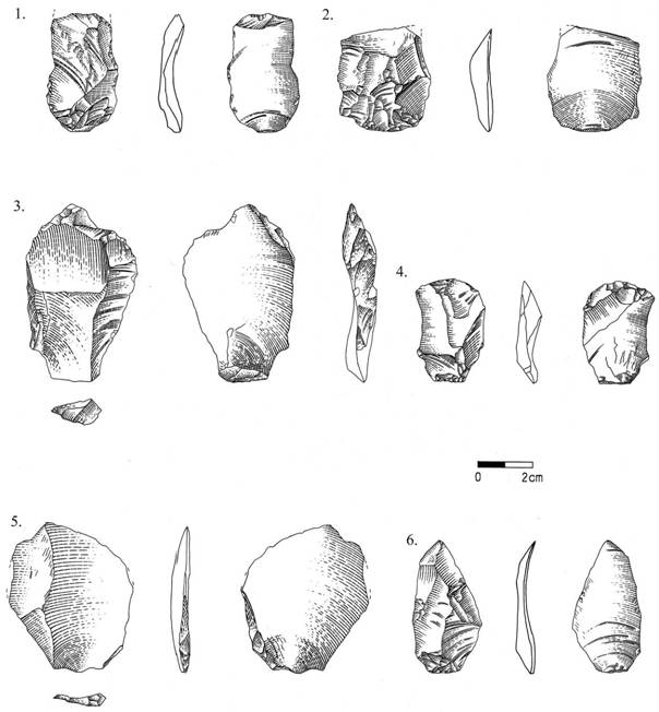
In accordance with many of its attributes, the archaeological assemblage was shown to include the thinning and finishing stages of bifacial tool production. However, as flint cores and flake tools with secondary modification were also recovered in this area, it is clear that the complete assemblage cannot be attributed exclusively to the production of bifaces (Goren-Inbar & Sharon 2006). For this reason, only debitage and items classified as originating in the production of handaxes (i.e., flakes, éclat de taille de biface and biface sharpening flakes; note that not a single flint cleaver was found in the excavations of GBY) were included in the analysis (Table 1; Figure 1). These components consist 72.64% of the entire flint assemblage from layers V-5 and V-6. While it is true that this selection cannot guarantee that all the artifacts included in the analysis necessarily originate from the reduction of handaxes, we believe that it provides a relatively good representation of this type of reduction sequence. One should note that unless a particular type of raw material was used exclusively for the production of bifaces, the analysis of an Acheulian assemblage by the present methods cannot differentiate between products originating from different reduction processes. Although the assemblages originating in Area C are dominated by flint, flint handaxes comprise less than 1% of the entire biface assemblage of the site. This, along with the evidence of rapid burial (see for example, Feibel 2001, 2004; Ashkenazi et al. 2010; Rabinovich et al. 2012), indicates that the great majority of the flint handaxes produced at the site were transported out of it by hominins (Sharon & Goren-Inbar 1998; Goren-Inbar & Sharon 2006).
Figure 1. Examples of artifacts from the archaeological assemblage. All artifacts are éclat de taille de biface except for no. 3 which is a flake. 1. #7635 Layer V-5; 2. #7633 Layer V-6; 3. #7667 Layer V-6; 4. #7677 Layer V-6; 5. #7657 Layer V-5; 6. #5485 Layer V-6. [Click here for a higher resolution image.]
Both archaeological and experimental assemblages were analyzed using an attribute analysis method designed for the GBY lithic assemblages (following Bar-Yosef & Goren-Inbar 1993; Goren-Inbar et al. in preparation). This method analyzes many preservation, typological and technological attributes to provide as comprehensive a description as possible. For the analysis of the experimental assemblage, however, only a selection of relevant technological attributes was employed. These include, among others, the size of each flake, the type of striking platform, the scar configuration of the dorsal face of the flakes, the direction of blow and the mode of breakage. However, as this study is concerned primarily with breakage, these attributes will not be dealt with here. The analysis of both archaeological and experimental assemblages included only artifacts larger than 2 cm in maximal dimension.
In the analysis employed at GBY, the breakage attribute describes the location of the breakage or breakages on each flake. According to this classification, each flake can be defined as either complete or broken. When it is broken, it is defined according to the location of the breakage, such as a proximally, distally or laterally broken flake. When the flake presents more than a single breakage, it is defined according to the locations of all the breakages; for example, a proximally and distally broken flake or laterally and distally broken flake. In this method an item is defined as a fragment if it is too broken to be oriented. The advantage of this classification method is that it provides a high descriptive resolution that is capable of detecting significant patterns in the locations of the breakages. However, it has two drawbacks, especially in respect to the computerized post-depositional breakage simulation model. These are its high complexity and lack of hierarchy. To address these issues, a second classification method for the description of broken pieces was employed. This method is a modification of the debitage classification method presented by Sullivan and Rozen (1985). The method consists of the hierarchical description of breakages based on the various feature retained on each piece. According to this classification, an artifact is classified as a fragment (FT) if it has no discernible remnant of its striking platform; as a split flake (SF) if it presents a sheared axis of flaking and a split striking platform (éclat siret); as a proximal flake (PF) if it has a complete striking platform and one or more signs of breakage on the distal end or one of the lateral margins; and, finally, a complete flake (CO) only if all of its margins are undamaged (no signs of breakage). The proximal flake class is further subdivided into proximal flake with a single breakage (PFS) and proximal flake with multiple breakages (PFM).
This hierarchical method reduces the descriptive resolution of the former classification method into three main categories: complete items, items with an intact proximal end (proximal flakes with a single or multiple breakages) and items lacking a complete proximal end (fragments). Naturally, from an analytical point of view the high-resolution classification is preferable to the hierarchical classification. However, we have decided to use this method in the model simulations because of its simplicity and hierarchical nature, which allow the simulation of additional breakage events in a simple and straightforward manner. For example, assuming that a complete flake is broken into two pieces, the hierarchical method will necessarily classify these two pieces as a proximal flake and a fragment, while in the GBY method there are many more possible classifications with regard to its location on the original item. For this reason, in order to allow the simulation of post-depositional breakage, both the archaeological and experimental assemblages were described using the hierarchical method in addition to the high-resolution breakage classification. The conversion of values was performed in accordance to the following criteria (Table 2). Distally or laterally broken flakes (i.e., broken flakes with a complete proximal end) were reclassified as proximal flakes with a single breakage (PFS). Similarly, flakes with multiple breakages but with a complete proximal end were reclassified as proximal flakes with multiple breakages (PFM). Proximally broken flakes or flakes with multiple breakages, one of which is proximal (i.e., flakes without an intact proximal end) were reclassified as fragments (FT). Non-orientable items that were classified as fragments in the high-resolution classification method retained their classification and were included in the fragment category of the hierarchical classification. Complete flakes and flakes with siret breakage also retained their classification.
Table 2. Conversion terminology for the two methods for classification of breaks.
|
High-resolution breakage pattern |
Hierarchical breakage pattern |
|
Complete flake |
Complete flake |
|
Distally broken flake (proximal end intact) |
Proximal flake with a single breakage |
|
Laterally broken flake (proximal end intact) |
Proximal flake with a single breakage |
|
Proximally broken flake |
Fragment |
|
Distally and laterally broken flake (proximal end intact) |
Proximal flake with multiple breakages |
|
Distally and proximally broken flake (broken proximal end) |
Fragment |
|
Proximally and laterally broken flake |
Fragment |
|
Fragment (non-orientable broken flake) |
Fragment |
|
Split flake |
Split flake |
The breakage patterns presented by the experimental assemblages are strictly limited to the production phase and not influenced by any taphonomic agent. Therefore, it could safely be assumed that if such an assemblage were a component of the archaeological record and had been subjected to further breakage caused by post-depositional processes (such as high-energy fluvial transport), its original breakage pattern would have been changed. The computerized post-depositional breakage simulation model was designed to attempt an assessment of the effects that such processes may have had on the pattern and frequency of breakages. The computerized model was built as a stand-alone program using Python’s Integrated Development Environment version 2.7.5.
The hierarchical classification method is of great importance to this model, as it allows prediction of the outcomes of a breakage event based on the type of item that is broken. For example, a complete flake subjected to breakage will no longer be classified as a complete flake but will yield a proximal flake and one or more additional fragments. This trait was used as the basis for the model’s simulation of the effects of post-depositional processes on the breakage pattern.
The model is limited to a single aspect of the physical state of the artifact and ignores other aspects such as abrasion, patination and spatial distribution, which may be other effects of post-depositional processes. The basic assumption underlying this model is that breakage caused by post-depositional processes simply inflicts additional breakages on an existing assemblage. The input of the model consists of the absolute number of items in each breakage category of the hierarchical classification method and the number of additional breakage events to which the assemblage is subjected. The user also selects the number of requested simulations for a given assemblage. The results obtained by a set of simulations are then averaged to provide a more robust prediction. The results are presented as absolute numbers and the frequency of each category of items.
Post-depositional breakages, whether anthropogenic or not, are unpredictable due to the abundance and complexity of factors involved in the process. Therefore, the item to be subjected to a breakage event is selected randomly out of all items in a given assemblage. The probability of selecting an item from a particular breakage category is directly related to the frequency of that category in the assemblage. It should be noted that this assumption is a somewhat simplified version of a realistic scenario in which flakes with a larger surface area and smaller thickness are more prone to breakage than items with a smaller surface area and greater thickness. Such trends, which are based on the correlations between the different dimensions of flakes, are inherent to the basic principles of fracture mechanics. We avoided introducing such variables into the model for the sake of simplicity. Thus, the chance of each type of item being selected is directly dependent on its occurrence in the assemblage. For example, if the assemblage is composed of 40% proximal flakes and 60% fragments, a fragment is more likely than a proximal flake to be broken. The outcome of each breakage event is hence dictated by the frequencies of the different breakage categories.
The model simulates the breakage in the following manner: for each additional breakage event an item from one of the categories is selected to be broken, based on their frequency in the assemblage. Figure 2 is a flow chart illustrating the mechanism of the simulation which describes step by step the process of modeling that is also described as follows:
If a complete flake is selected, one item is subtracted from the CO category. This breakage could result in two or three new pieces. The possibility of a single breakage event fragmenting one piece into three is documented in the presence of items with multiple breaks in the experimental assemblages, where each item was subjected only to a single high-energy event (i.e., its removal). The probability of such an event in the model was determined according to the frequency of items with multiple breakages in the combined experimental assemblages. If the item breaks into two pieces, one item is added to the PFS category and another to the FT category. If the items break into three pieces, one item is added to the PFM category and two items are added to the FT category.
If a proximal flake with a single breakage is selected, one item is subtracted from the PFS category and one item is added to the PFM category. If the item breaks into two pieces, one additional item is added to the FT category, while if the item breaks into three, two items are added to this category.
If a proximal flake with multiple breakages is selected, no items are subtracted from any of the categories. If the item breaks into two pieces, one additional item is added to the FT category, while if the item breaks into three, two items are added to this category.
If a split flake is selected, no items are subtracted from any of the categories. If the item breaks into two pieces then one additional item is added to the FT category, while if the item breaks into three, two items are added to this category.
If a fragment is selected, no items are subtracted from any of the categories. If the item breaks into two pieces, one additional item is added to the FT category, while if the item breaks into three, two items are added to this category.
Simulations were performed on the breakage pattern of the combined experimental assemblage, simulating the breakage of 10%, 20% and 30% of the items. A series of ten simulations was conducted for each group of additional breakages.
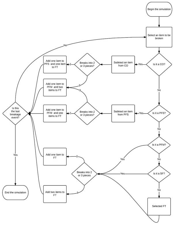
Figure 2. A flowchart describing the model’s algorithm. An item to be broken is randomly selected. The frequencies of the different breakage categories making up the assemblage are changed in accordance with the type of item selected. CO = complete flake, PFS = proximal flake with a single breakage, PFM = proximal flake with multiple breakages, SF = split flake, FT = fragment. [Click here for a higher resolution image.]
The breakage patterns and frequencies of the six experimental assemblages are first presented here using both classification methods (Table 3). The results of the experimental and archaeological breakage patterns are presented and compared in detail using the high-resolution classification method. However, since the simulations of post-depositional breakage are based on the hierarchical classification method, their results are discussed and compared to the archaeological assemblage using this classification method. The results of the hierarchical classification method are presented at three levels. The first is the ratio of complete to broken flakes. This level represents the coarsest level of analysis and shows the proportion of complete flakes relative to the total amount of broken flakes and fragments in each assemblage. The second level presents the distribution of breakage types amongst the broken items in the assemblage. The third level displays the breakage type distribution amongst the proximal flake category. This three-level approach enables the systematic characterization of the breakage pattern in each assemblage.
Table 3. High-resolution and hierarchical breakage classifications of experimental and archaeological assemblages. Abbreviations: CE - Combined Experimental; TE - Total Experimental.
|
High-resolution classification |
||||||||||||||
|
C-35 |
C-36 |
C-37 |
C-45 |
C-50 |
CE |
GBY |
||||||||
|
Category |
N |
% |
N |
% |
N |
% |
N |
% |
N |
% |
N |
% |
N |
% |
|
Complete |
69 |
28.99 |
34 |
33.01 |
34 |
47.89 |
43 |
37.39 |
18 |
28.57 |
198 |
33.56 |
237 |
51.30 |
|
Distal |
43 |
18.07 |
16 |
15.53 |
12 |
16.90 |
16 |
13.91 |
11 |
17.46 |
98 |
16.61 |
76 |
16.45 |
|
Lateral |
15 |
6.30 |
7 |
6.80 |
7 |
9.86 |
16 |
13.91 |
7 |
11.11 |
52 |
8.81 |
26 |
5.63 |
|
Proximal |
26 |
10.92 |
23 |
22.33 |
11 |
15.49 |
18 |
15.65 |
7 |
11.11 |
85 |
14.41 |
40 |
8.66 |
|
Distal & Lateral |
15 |
6.30 |
4 |
3.88 |
2 |
2.82 |
8 |
6.96 |
8 |
12.70 |
37 |
6.27 |
18 |
3.90 |
|
Distal & Proximal |
33 |
13.87 |
11 |
10.68 |
1 |
1.41 |
2 |
1.74 |
0 |
0.00 |
47 |
7.97 |
15 |
3.25 |
|
Fragment |
15 |
6.30 |
1 |
0.97 |
0 |
0.00 |
6 |
5.22 |
4 |
6.35 |
26 |
4.41 |
41 |
8.87 |
|
Proximal & Lateral |
12 |
5.04 |
7 |
6.80 |
3 |
4.23 |
2 |
1.74 |
8 |
12.70 |
32 |
5.42 |
9 |
1.95 |
|
Split |
10 |
4.20 |
0 |
0.00 |
1 |
1.41 |
4 |
3.48 |
0 |
0.00 |
15 |
2.54 |
0 |
0.00 |
|
Total |
238 |
100 |
103 |
100 |
71 |
100 |
115 |
100 |
63 |
100 |
590 |
100 |
462 |
100 |
|
Hierarchical classification |
||||||||||||||
|
C-35 |
C-36 |
C-37 |
C-45 |
C-50 |
TE |
GBY |
||||||||
|
Category |
N |
% |
N |
% |
N |
% |
N |
% |
N |
% |
N |
% |
N |
% |
|
Complete |
69 |
28.99 |
34 |
33.01 |
34 |
47.89 |
43 |
37.39 |
18 |
28.57 |
198 |
33.56 |
237 |
51.30 |
|
Proximal Single |
58 |
24.37 |
23 |
22.33 |
19 |
26.76 |
32 |
27.83 |
18 |
28.57 |
150 |
25.42 |
102 |
22.08 |
|
Proximal Multiple |
15 |
6.30 |
4 |
3.88 |
2 |
2.82 |
8 |
6.96 |
8 |
12.70 |
37 |
6.27 |
18 |
3.90 |
|
Fragment |
86 |
36.13 |
42 |
40.78 |
15 |
21.13 |
28 |
24.35 |
19 |
30.16 |
190 |
32.20 |
105 |
22.73 |
|
Split |
10 |
4.20 |
0 |
0.00 |
1 |
1.41 |
4 |
3.48 |
0 |
0.00 |
15 |
2.54 |
0 |
0.00 |
|
Total |
238 |
100 |
103 |
100 |
71 |
100 |
115 |
100 |
63 |
100 |
590 |
100 |
462 |
100 |
To address the issue of similarity between the breakage of artifacts in the archaeological and experimental assemblages, comparison of a selected size attribute was carried out. A ratio was chosen for the comparison consisting of the surface area of an artifact divided by its thickness. This ratio is calculated by multiplying the length of each artifact by its width in order to assess its surface, a value that is then divided by its thickness. This ratio will increase as the surface area of the flake increases and its thickness decreases. Hence, when this index is higher the artifact has a greater chance of breaking if subjected to a high-energy event.
The surface/thickness ratio was calculated for each of the assemblages and for three different breakage categories, which were defined following the high-resolution classification method. These categories are complete, broken and fragments (Figure 3). Two main insights results from this comparison. The first is concerned with the variation in the values of the ratio between the breakage categories. While there is a pronounced similarity in values between the complete and broken categories, the values of the fragments category are significantly lower. This result is to be expected, given the fact that the fragments category is composed of small items that have broken off from items included in the two other categories. Thus, they will usually maintain a fairly constant thickness value, while their surface area becomes smaller. The similar values of the complete and broken categories indicate that items that are not extensively broken and hence could not be oriented still maintain a fairly constant ratio of surface to thickness. This trend is identical in the archaeological and experimental assemblages. The second insight is concerned with the differences between the archaeological and experimental assemblages. It is clear that the archaeological assemblage presents significantly lower values than the experimental one. This observation indicates that the artifacts of GBY are thicker in relation to their surface area than those in the experimental assemblage. Hence, the results of the comparison suggest that in conditions of an identical post-depositional process causing breakage, the artifacts in the archaeological assemblage will be less prone to breakage than those in the experimental one.
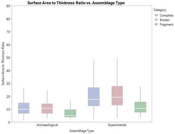
Figure 3. Box plots of surface area to thickness ratios of the different breakage categories and assemblage types.
It is apparent that all the experimental assemblages present an unequivocal majority of broken pieces (Table 3). Assemblage C-50 presents the highest breakage rate, 71.43% of the assemblage, while in assemblage C-37 only 52.11% of the items in the assemblage are broken. In the combined assemblage 66.44% of all pieces are not complete.
The most common breakage category in the combined experimental assemblage is that of distally broken flakes, 16.61% of the items. This category is the most common in all assemblages except C-45 and C-36 and ranges from 18.07% in C-35 to 13.91% in C-45. Following this category is that of proximally broken flakes, 14.41% of the items in the combined assemblage. This category ranges from 22.33% in C-36 to 10.92 in C-35 and is the most common in assemblages C-36 and C-45. The next most common category is that of laterally broken flakes, which comprises 8.81% of the items in the combined assemblage. It ranges from 13.91% in assemblage C-45 to 6.30% in assemblage C-35. These categories conclude the items with a single breakage (Table 3).
There are four categories of items with multiple breakages: distal and lateral, proximal and lateral, proximal and distal, and fragments. Generally, these categories are less frequent than those consisting of items with a single type of breakage. In the different experimental assemblages, each of the categories with multiple breakages usually comprises less than 7%, with a few exceptions in which one or two of these categories comprises more than 10% of the assemblage. In the combined assemblage these categories account for 24.07% of the items, in contrast to the 39.83% represented by the previous three breakage categories.
The final breakage category is split flakes. This category is singular in that it can be formed only during the production phase. The category comprises 2.54% of the artifacts in the combined assemblage, reaching a maximum of 4.20% in assemblage C-35, while it is completely absent from others such as C-36 and C-50 (Table 3).
In general, the distribution of breakage categories among the different experimental assemblages is fairly uniform. Although there are variations in the frequencies of the different categories, they are minor and do not substantially affects the general breakage pattern. The variations could be related to minor differences in the specific raw materials used or to incidental differences in particular reduction sequences performed by the same knapper.
The ratio of complete to broken flakes is substantially higher in the GBY archaeological assemblage (Table 3). The complete flakes form more than half of the assemblage (51.30%). Even the experimental assemblage with the highest number of complete flakes (C-37) has 3.41% fewer complete flakes than the archaeological assemblage.
Regarding the distribution of breakage types, the general trend observed is one of similarity to the experimental assemblage, with a few specific differences. Within the category of broken items, the distally broken flakes are the most common category (16.45% of the items). However, in contrast with the combined experimental assemblage, all the other breakage categories are distributed in a fairly homogenous manner, with none exceeding 10% of the items. Nonetheless, similarly to the combined experimental assemblage, the categories of items with a single breakage make up 30.74% of the assemblage, while the categories of items with multiple breakages represent only 17.97% of the cases. It should be noted that fragments are twice as common in the archaeological assemblage, while split flakes are absent.
The breakage pattern of the combined experimental assemblage formed the basis for simulations of the effect of post-depositional breakage. The results present the predicted breakage pattern of the combined experimental assemblages after 59 (10%), 118 (20%) and 177 (30%) additional breaks. As the model uses the hierarchical classification method, the results of the simulations are presented using the three-level method (Figure 4; Table 4).
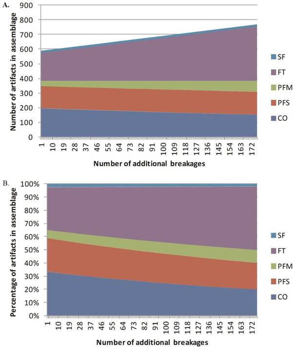
Figure 4. Curves representing changes to the breakage patterns with increasing number of additional breakages caused by a post-depositional process. Notice the increase in the absolute number of artifacts in the assemblage. A. Absolute change in the breakage categories. B. Proportional change in breakage categories.
The most prominent effect of the addition of breaks was an increase in the absolute number of broken items in each assemblage. The increase was in direct proportion to the number of additional breaks, as each breakage event adds at least one item to the assemblage. Naturally, this addition also causes an increase in the absolute numbers of broken items and a corresponding decrease in the complete to broken ratio in the assemblages. The frequencies of broken items in the assemblage increased by 5.91%, 10.18% and 13.71% after 59, 118 and 177 additional breakage events respectively (Figure 4).
Table 4. Breakage assemblages described by hierarchical classification of archaeological, experimental and post-depositional simulation.
|
Assemblage |
GBY |
Combined experimental pristine |
Combined experimental after 59 additional breaks |
Combined experimental after 118 additional breaks |
Combined experimental after 177 additional breaks |
|||||
|
N |
% |
N |
% |
N |
% |
N |
% |
N |
% |
|
|
Complete |
237 |
51.30 |
198 |
33.56 |
180 |
27.65 |
166 |
23.38 |
153 |
19.84 |
|
Broken |
225 |
48.70 |
392 |
66.44 |
471 |
72.35 |
544 |
76.62 |
618 |
80.16 |
|
Total |
462 |
100.00 |
590 |
100.00 |
651 |
100.00 |
710 |
100.00 |
771 |
100.00 |
|
N |
% |
N |
% |
N |
% |
N |
% |
N |
% |
|
|
Proximal Flake |
120 |
53.33 |
187 |
47.70 |
206 |
43.74 |
219 |
40.26 |
232 |
37.54 |
|
Fragment |
105 |
46.67 |
190 |
48.47 |
250 |
53.08 |
310 |
56.99 |
371 |
60.03 |
|
Split |
0 |
0.00 |
15 |
3.83 |
15 |
3.18 |
15 |
2.76 |
15 |
2.43 |
|
Total |
225 |
100.00 |
392 |
100.00 |
471 |
100.00 |
544 |
100.00 |
618 |
100.00 |
|
N |
% |
N |
% |
N |
% |
N |
% |
N |
% |
|
|
Proximal Single |
102 |
85.00 |
150 |
80.21 |
153 |
74.27 |
153 |
69.86 |
155 |
66.81 |
|
Proximal Multiple |
18 |
15.00 |
37 |
19.79 |
53 |
25.73 |
66 |
30.14 |
77 |
33.19 |
|
Total |
120 |
100.00 |
187 |
100.00 |
206 |
100.00 |
219 |
100.00 |
232 |
100.00 |
The proportion of breakage types in the assemblage was also greatly affected by the additional breaks. The proportion of proximal flakes decreased by 3.96%, 7.45% and 10.16%, simultaneously with an equivalent increase in the proportions of fragments for the three additional breakage groups respectively. The proportion of the split flake category was only slightly modified, giving its initial rarity in the experimental assemblages and the fact that it can be created only during the production phase (Figure 4).
Finally, the addition of breakage events altered the proportion of the proximal flake breakage types. While in the combined experimental assemblage proximal flakes with a single breakage formed slightly more than 80% of all proximal flakes, this amount gradually decreased by 5.94%, 10.35% and 13.40% with the addition of breakages.
The combination of the results of all the experimental assemblages can be used as a general reference point and a reliable estimation of breakage patterns caused in the final stages of Acheulian bifacial knapping. Although some variability is observed among the different assemblages, it can be seen as a natural intrinsic variability that occurs during a homogenous knapping process by a single expert knapper. The main trends that appear in all experimental assemblages, and thus are also expressed in the combined sample, are as follows:
The assemblage is characterized by a majority of broken pieces in frequencies ranging from 52.11% to 71.43%.
There is a relatively high frequency of broken artifacts with a single breakage, ranging between 44.66% and 35.29% of the assemblages, with proximally or distally broken flakes being more frequent than laterally broken ones.
There is a relatively low frequency of broken artifacts with multiple breaks, ranging between 31.75% and 8.45% of the items. In most cases none of the breakage categories exceeds 10%.
There is a low frequency, not exceeding 5% and at times a total absence, of split flakes.
The importance of this pattern lies in the fact that it represents only breaks that occur during the production phase. As the assemblages are experimental, the artifacts are completely free of the effects of use or post-depositional processes. Hence, they demonstrate that a majority of broken items in an assemblage is inherent to the final stages of Acheulian bifacial knapping, regardless of any processes to which the artifacts may have been subjected during the discard and post-depositional phases of their life history
Another important aspect highlighted by the study of these assemblages relates to the variability that may exist between similar assemblages. All of the six experimental assemblages used here were produced by the same expert knapper using similar reduction sequences and knapping techniques. Nevertheless, some variability is apparent in their breakage patterns. This observation should be noted and taken as a warning of the fact that knapping is a highly dynamic process that may produce variable results under the same conditions.
The breakage simulations of the effects of the post-depositional process also provide some important insights. With increased intensity and duration of such process a clear trend can be seen, which is directly expressed in the increase of the amount of additional breakages to which the assemblage is subjected (Figure 4). As the number of additional breakages increases, the absolute number and proportions of complete flakes in the assemblage decreases. Another effect is a decrease in the proportions of proximal flakes, even though their absolute number increases. This effect is due to the fact that the increase in the absolute number of fragments is substantially greater than that in the proximal flake category, as each breakage event adds at least one fragment to the assemblage. The final effect is that of a decrease in the proportions of proximal flakes with a single breakage, along with an increase of proximal flakes with multiple breakages.
The mode of change in the different categories derives from their hierarchical definition. The complete flake category diminishes continuously, as no new complete flakes are added to the assemblage and no fragments or proximal flakes with multiple breakages are removed from it. This causes the proportions of those categories in the assemblage to decrease and increase respectively with intensification of the post-depositional process. The category of proximal flakes with a single breakage, which can both gain and lose items, maintains a fairly constant absolute number of items, although its proportion decreases moderately due to the increase in the number of items in the assemblage. A similar trend is seen in the split flake category, which can neither gain nor lose items.
The comparison between the original breakage pattern of the combined experimental assemblage and those provided by the model yields a pattern that could be applicable to interpretations of the taphonomic integrity of archaeological assemblages. This pattern consists of a low ratio of complete to broken flakes, a low ratio of proximal flakes to fragments among the broken items, and a low ratio of proximal flakes with a single breakage to proximal flakes with multiple breakages. Such a breakage pattern could indicate that an assemblage was subjected to breakage caused by post-depositional processes.
The breakage pattern of the GBY Acheulian archaeological assemblages provides an intriguing picture: not only is the pattern the opposite of one that possibly indicates the influence of post-depositional processes, but it actually hints at a more pristine state than that of the combined experimental assemblage. The ratio of complete to broken flakes is substantially higher than that seen in any of the experimental assemblages. Applying the high-resolution method to the analysis of the breakage of the experimental and the GBY assemblages results in generally similar patterns. Broken items with a single break have a high frequency of 30.74%, with the highest being that of distally broken flakes and the lowest of laterally broken flakes. The broken items with multiple breaks comprise 17.97%, with none of the categories exceeding 10% and split flakes are absent.
When the breakage pattern is examined using the hierarchical method, the ratio of proximal flakes to fragments among the broken items is higher than that seen in the combined experimental assemblage, but is similar to those seen in assemblages C-37, C-45 and C-50. The ratio of proximal flakes with a single breakage to those with multiple breaks is moderately higher than that of the combined experimental assemblage, but is similar to those of assemblages C-36 and C-37.
The similarities and differences between the archaeological and experimental assemblages provide some insights into the taphonomic state of the GBY assemblages. The proportion of proximal flakes among broken pieces and the ratio of proximal flakes with a single break to those with multiple breaks indicate that the breakage pattern of the GBY assemblages is most similar to that of the combined experimental assemblage. However, the fact that the ratio of complete to broken flakes is substantially higher in the archaeological assemblage is a peculiarity that may have several reasons. For example, the presence of cores and flake tools in the area and layers in which the GBY assemblages originate suggests that some of the unmodified flakes included in the sample were probably derived from other reduction sequences, unrelated to the production of bifaces. Furthermore, the significantly lower surface area to thickness ratio in this assemblage may have reduced the frequency of breaks caused during production. It should be noted that even when examining this ratio only for those items that are defined as éclat de taille de biface and biface sharpening flakes, the values are still lower than those seen in the experimental assemblage. Finally, the frequencies of breaks that occur during production may be greatly influenced by the knapper as well as by random factors related to specific individual reduction sequences, as indicated by the experimental assemblages. Notwithstanding the fact that the experimental reduction sequences are generally identical to those reconstructed for the GBY assemblages, the lower values of the surface area to thickness ratio may be the outcomes of such factors.
Nonetheless, the high complete to broken ratio, which contrasts with the trend of a decreasing ratio with increasing intensity of the post-depositional process, highlights the pristine taphonomic state of the GBY assemblage. These observations on the breakage pattern of the GBY assemblages strongly suggest that it was never subjected to intense or prolonged post-depositional processes causing breakage. Therefore, the observed breakage pattern probably indicates that most of the breaks were caused during the knapping process.
Notwithstanding these conclusions, a word of caution is in order. Naturally, both the experimental approach and the simulation modelling simplify the extensive complexity that exists in the deposition of archaeological assemblages. Issues such as the effect of varying size and reduction sequence of items on breakage, assemblage mixing, winnowing and collection bias were not considered in the model. For archaeological assemblages, these issues too may have a strong effect on the observed breakage pattern. However, the breakage patterns of the pristine experimental assemblage and the simulation of the effects of post-depositional breakage provide some degree of referential framework for the taphonomic state of debitage created during biface production. Moreover, the identification of a systematic trend of breakage associated with an increase in duration and intensity of post-depositional processes may permit a better understanding of the nature of lithic assemblages.
With regard to the GBY assemblage, the current conclusions join various other lines of evidence supporting the notion of rapid burial and sealing of the archaeological horizons. These consist, among others, of the recovery of abundant microartifacts from Layers V-5 and V-6 (and all others), providing an indication of a lack of winnowing. Furthermore, microartifacts were found spatially clustered, for example by raw material and by burning (phantom hearths) (Alperson-Afil 2008; Alperson-Afil et al. 2009; Alperson-Afil & Goren-Inbar 2010). The presence of unsorted macroartifacts, different-sized mammal bones, small fragments of micromammals (Rabinovich & Biton 2011), small botanical remains (Melamed et al. 2011), and conjoinable bones of medium-sized and large mammal bones (Rabinovich et al. 2012) all provide additional indications of minimal post-depositional effects (Goren-Inbar et al. in preparation). Hence, the results and conclusions of the present study provide further support for the generally undisturbed taphonomic state of the lithic assemblage from Area C at the site of GBY.
The systematic analysis of the breakage patterns of experimental Acheulian biface production assemblages, the simulation of effects of post-depositional breaks and their comparison to the GBY archaeological assemblages have provided several valuable insights. First, it was shown that the final stages of bifacial knapping produce assemblages that are characterized by a high ratio of broken items. Second, it was shown that breakage caused by post-depositional processes changes the production breakage pattern in accordance with a well-defined and systematic trend. Moreover, the higher the number of additional breaks, the larger the differences in the breakage patterns. Comparison of the experimental and modeling results with the biface production debitage assemblages of GBY indicates that the latter were probably not subjected to breakage caused by post-depositional processes. These insights may assist in achieving a more accurate interpretation of the taphonomic state of other archaeological assemblages.
This research was supported by the Israel Science Foundation (grant no. 27/12). We thank Bo Madsen for producing the experimental assemblages, Gonen Sharon for curating the materials used in this study, Paolo Giunti for the drawing of the artifacts, and Alon Silva for his helpful advice on the programming of the model. Sue Gorodetsky edited the manuscript with her usual professionalism and dedication.
Alperson-Afil, N. 2008, Continual fire-making by hominins at Gesher Benot Ya‘aqov, Israel. Quaternary Science Reviews, 27(17): 1733-1739. doi:10.1016/j.quascirev.2008.06.009
Alperson-Afil, N. & Goren-Inbar, N. 2010, The Acheulian site of Gesher Benot Ya’aqov volume II: Ancient flames and controlled use of fire. Springer, Dordrecht, 120 p. doi:10.1007/978-90-481-3765-7
Alperson-Afil, N., Sharon, G., Kislev, M., Melamed, Y., Zohar, I., Ashkenazi, S., Rabinovich, R., Biton, R., Werker, E. & Hartman, G. 2009, Spatial organization of hominin activities at Gesher Benot Ya’aqov, Israel. Science, 326(5960): 1677-1680. doi:10.1126/science.1180695
Amick, D.S., Mauldin, R.P. & Tomka, S.A. 1988, An evaluation of debitage produced by experimental bifacial core reduction of a Georgetown chert nodule. Lithic Technology, 17(1): 26-36. Stable URL: http://www.jstor.org/stable/23272827
Andrefsky, W. 2005, Lithics: Macroscopic approaches to analysis. Cambridge University Press, Cambridge, 321 p.
Ashkenazi, S., Klass, K., Mienis, H.K., Spiro, B. & Abel, R. 2010, Fossil embryos and adult Viviparidae from the Early–Middle Pleistocene of Gesher Benot Ya’aqov, Israel: ecology, longevity and fecundity. Lethaia, 43(1): 116-127. doi:10.1111/j.1502-3931.2009.00178.x
Bar-Yosef, O. & Goren-Inbar, N. 1993, The lithic assemblage of Ubeidiya. A lower paleolithic site in the Jordan Valley. Institute of Archaeology, Hebrew University of Jerusalem, Jerusalem, 266 p.
Bertran, P., Lenoble, A., Todisco, D., Desrosiers, P.M. & Sørensen, M. 2012, Particle size distribution of lithic assemblages and taphonomy of Palaeolithic sites. Journal of Archaeological Science, 39(10): 3148-3166. doi:10.1016/j.jas.2012.04.055
Chambers, J. 2003, Like a rolling stone? the identification of fluvial transportation damage signatures on secondary context bifaces. Lithics, 24: 66-77.
Cotterell, B., Kamminga, J. & Dickson, F. 1985, The essential mechanics of conchoidal flaking. International Journal of Fracture, 29(4): 205-221. doi:10.1007/BF00125471
Debénath, A. & Dibble, H.L. 1994, Handbook of Paleolithic Typology: Lower and middle paleolithic of Europe. University of Pennsylvania Museum, Philadelphia, 256 p.
Feibel, C.S. 2001, Archaeological sediments in lake margin environments. In: Sediments in archaeological context,(Stein, J. K., & Farrand, W. R., Eds.), University of Utah Press, Salt Lake City: p. 127-147.
Feibel, C.S. 2004, Quaternary lake margins of the Levant Rift Valley. In: Human Paleoecology in the Levantine Corridor, (Goren-Inbar, N., & Speth, J. D., Eds.), Oxbow Books, Oxford: p. 21-36.
Goren-Inbar, N. & Sharon, G. 2006, Invisible handaxes and visible Acheulian biface technology at Gesher Benot Ya‘aqov, Israel. In: Axe age: Acheulian tool-making from quarry to discard, (Goren-Inbar, N., & Sharon, G., Eds.), Routledge, London: p. 111-135.
Goren-Inbar, N., Sharon, G., Alperson-Afil, N. & Herzlinger, G. In preparation, The Acheulian Site of Gesher Benot Ya‘aqov Vol IV: The Lithic Assemblages. Springer, New-York.
Grosman, L., Sharon, G., Goldman-Neuman, T., Smikt, O. & Smilansky, U. 2011, Studying post depositional damage on Acheulian bifaces using 3-D scanning. Journal of Human Evolution, 60(4): 398-406. doi:10.1016/j.jhevol.2010.02.004
Hiscock, P. 1985, The need for a taphonomic perspective in stone artefact analysis. Queensland Archaeological Research, 2: 82-97. URL: https://www.library.uq.edu.au/ojs/index.php/qar/article/view/310
Hiscock, P. 2002, Quantifying the size of artefact assemblages. Journal of Archaeological Science, 29(3): 251-258. doi:10.1006/jasc.2001.0705
Hosfield, R. & Chambers, J. 2003, Flake modifications during fluvial transportation: three cautionary tales. Lithics, 24: 57-65.
Jennings, T.A. 2011, Experimental production of bending and radial flake fractures and implications for lithic technologies. Journal of Archaeological Science, 38(12): 3644-3651. doi:10.1016/j.jas.2011.08.035
Madsen, B. & Goren-Inbar, N. 2004, Acheulian giant core technology and beyond: an archaeological and experimental case study. Eurasian Prehistory, 2(1): 3-52.
Mallouf, R.J. 1982, An analysis of plow-damaged chert artifacts: the Brookeen Creek cache (41HI86), Hill County, Texas. Journal of Field Archaeology, 9(1): 79-98. doi:10.1179/009346982791974651
Mauldin, R.P. & Amick, D.S. 1989, Investigating patterning in debitage from experimental bifacial core reduction. In: Experiments in lithic technology, (Amick, D.S., & Mauldin, R. P., Eds.), BAR International Series Vol. 528, Archaeopress, Oxford: p. 67-88.
Melamed, Y., Kislev, M., Weiss, E. & Simchoni, O. 2011, Extinction of water plants in the Hula Valley: Evidence for climate change. Journal of human evolution, 60(4): 320-327. doi:10.1016/j.jhevol.2010.07.025
Newcomer, M.H. 1971, Some quantitative experiments in handaxe manufacture. World Archaeology, 3(1): 85-94. doi:10.1080/00438243.1971.9979493
Rabinovich, R. & Biton, R. 2011, The Early–Middle Pleistocene faunal assemblages of Gesher Benot Ya‘aqov: Inter-site variability. Journal of human evolution, 60(4): 357-374. doi:10.1016/j.jhevol.2010.12.002
Rabinovich, R., Gaudzinski-Windheuser, S., Kindler, L. & Goren-Inbar, N. 2012, The Acheulian Site of Gesher Benot Ya‘aqov Vol III: Vertebrate Paleobiology and Paleoanthropology. Springer, Dordrecht, 270 p. doi:10.1007/978-94-007-2159-3
Rust, J.A. & Earl, D. 2011, Rebuttal: Disturbance to Surface Lithic Components of Archaeological Sites by Drill Seeding. Rangeland Ecology & Management, 64(5): 548-551. doi:10.2111/REM-D-09-00069.1
Schoville, B.J. 2014, Testing a taphonomic predictive model of edge damage formation with Middle Stone Age points from Pinnacle Point Cave 13B and Die Kelders Cave 1, South Africa. Journal of Archaeological Science, 48: 84-95. doi:10.1016/j.jas.2013.10.002
Sharon, G. 2007, Acheulian large flake industries: technology, chronology, and significance. BAR International Series Vol. 1701, Archaeopress, Oxford, 236 p.
Sharon, G. & Goren-Inbar, N. 1998, Soft percussor use at the Gesher Benot Ya‘aqov Acheulian site. Journal of Israel Prehistoric Society, 28: 55-79. Stable URL: http://www.jstor.org/stable/23380075
Sullivan, A.P. & Rozen, K.C. 1985, Debitage analysis and archaeological interpretation. American Antiquity, 50(4): 755-779. Stable URL: http://www.jstor.org/stable/280165